Waterman, control without cables.
The Waterman copies a signal from one point to another with no cable and no cellular network. It creates its own LoRa radio link between the units, up to 15 km line of sight.
1 · What it is
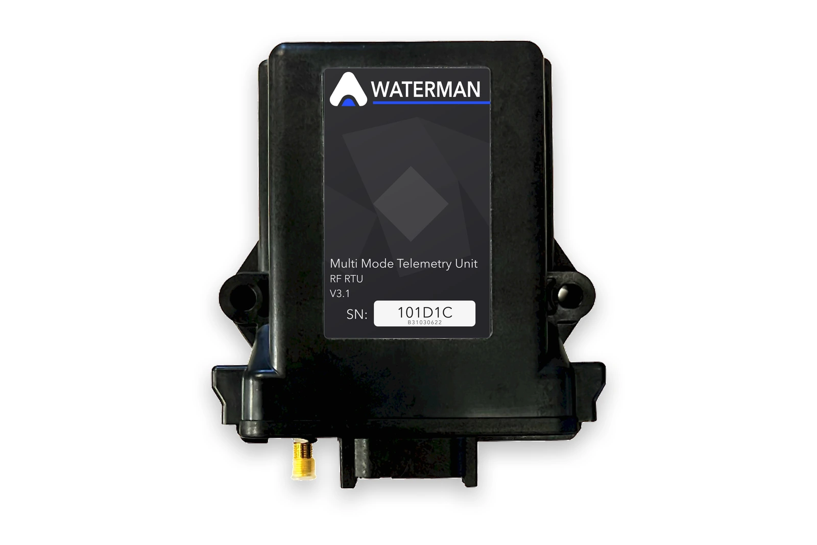
The Augos Waterman is a wireless telemetry unit that copies signals from one point to another over LoRa radio. Units are installed in pairs or small groups: an input wired into one unit is reproduced on the matching output of another, up to 15 km line of sight, with no cable and no cellular network between them.
Where the far end only has to report an on-off state and there is no power to run a second Waterman, the tank-to-pump kit pairs a Waterman with a battery-powered state sensor instead of a second unit.
2 · How it works
One unit goes where the signal originates. The other goes at the equipment that acts on it, with its relay wired into the starter or control circuit.
Each unit has one input and one output for an on-off signal, one input and one output for a sensor signal, and an RS-485 port. The on-off pair takes what a float switch, a trip relay or a running contact gives you; the sensor pair takes a 4-20 mA or 1-5 V transmitter. In wiring terms that's a dry-contact input, a relay output, a 1-5 V or 4-20 mA analogue input, a 0-5 V analogue output, and Modbus RTU passed straight through over RS-485.
The unit doesn't know what the sensor is measuring, and it doesn't hand the far end a number in bar or metres. It sends the signal as a percentage of the transmitter's range and puts it out as 0 to 5 V, so a 4-20 mA transmitter goes in at one end and 0-5 V comes out at the other. Scale that 0-5 V in the drive, controller or PLC to match the transmitter's range, the same as you would if the transmitter were wired to it directly.
A unit sends a message the instant one of its inputs changes, and another every 15 seconds to say it's still alive. If it stops being heard from for three minutes, the outputs at the other end drop out: the relay opens and the sensor output falls to zero. A flat battery, a snapped aerial or a unit somebody switched off leaves the far end open rather than stuck on the last instruction it was given. Wire the circuit so that open is the safe position, and a lost link stops the pump instead of leaving it running.
Setting a unit up is a bank of small DIP switches on the board, protected by a jumper. They set which mode it runs in, which unit it is, which channel it uses, how far it has to reach and what kind of sensor is connected to it. No laptop, no app, nothing to install. The screen on the front shows what the unit is doing and how strong its signal is, so you can commission it and find faults standing in front of it.
Each unit ships with a 5 m antenna cable and a high-range antenna, so the aerial goes where the signal is rather than where the box is. Where the box has to sit low, in a panel or inside a building, 10 m and 20 m cables let you take the aerial up a pole or onto a roof.
3 · Switching the pump
The Waterman's output is a 12 V relay giving a clean dry contact, and it is pilot duty only. It switches a DC circuit of 24 V or less. It must never switch mains, a 230 V AC contactor coil, or anything above 24 V DC. Everything the Waterman controls is switched through something else, and there are three ways that goes together.
| What's at the pump | How the Waterman drives it | What we need from you |
|---|---|---|
| No contactor | Augos supplies a contactor sized to the pump with a 12 or 24 V DC coil. The Waterman relay switches the coil, the contactor switches the motor. | The pump motor rating in kW, or the breaker or overload rating in amps, and whether the supply is 230 V single phase or 400 V three phase. |
| A contactor or starter already installed | A DC coil of 24 V or less is switched directly by the Waterman relay. An AC coil, 230 V being the usual one on motor starters, or any DC coil above 24 V, is switched through an interposing relay: the Waterman switches the small relay's DC coil, and that relay's contact switches the contactor coil. | The coil voltage, printed on the coil next to its A1 and A2 terminals. |
| A VSD or soft starter | The dry contact goes straight into the drive's start-stop digital input. No contactor and no interposing relay. The drive keeps its own motor protection, dry-run and pressure functions. | That the drive has a free digital input running on a DC control voltage of 24 V or less. |
As a rough guide for a new contactor on a 400 V three-phase supply, AC-3 rated: 4 kW needs 9 A, 5.5 kW needs 12 A, 7.5 kW needs 18 A, 11 kW needs 25 A and 15 kW needs 32 A. We size it properly off the actual nameplate.
4 · Use cases
Stopping the pump when a pivot trips
When a centre pivot trips, the pump doesn't know about it and carries on running. Water piles up where the pivot stopped, that span gets drowned, and the pump burns power until somebody drives out and finds it.
Wire the pivot panel's safety contact into the unit at the pivot. At the pump house, the relay goes into the VSD's run-enable, or into a DC pilot relay sitting in the starter's hold circuit. The pivot trips, the contact opens, the pump stops. The same link works in reverse, so you can start the pivot from the pump room instead of driving out to it. Up to seven pivots can share one unit at the pump house, and the pump runs as long as any of them is running.
Keeping the pressure right at the far end of an irrigation line
The pressure that matters is at the far end of the line, not at the pump. A centre pivot walking over uneven ground changes what it needs as it goes: climbing a rise the inlet pressure falls away, and coming back down the same pump speed over-pressures the line. A gauge at the pump house does not show either.
Put a 4-20 mA pressure transmitter at the pivot inlet or the end of the line and wire it into the unit there. The unit at the pump station puts that signal out as 0 to 5 V and hands it to the variable-speed drive, which speeds the pump up or slows it down to hold the pressure you set. With several lines running, the pump-station unit passes on the lowest pressure among the lines that are running, so the pump is always working to whichever of them is struggling most. Its relay closes while any line is running, and that is the pump's start signal.
Filling a tank or dam with a float switch
Wire a float switch in the dam or header tank into the unit there. The relay in the unit at the pump follows the float: float closed, the pump runs; float open, the pump stops. The pump's own running contact travels back the other way on the same link, so a lamp at the dam shows you the pump is actually turning, not just that the float asked for it.
Up to seven tanks can call the same pump. Wire the float so that calling for water is the closed position. If the link is ever lost, the pump stops rather than being left to overfill the tank.
Where the tank end has no power and only has to report the float, use the tank-to-pump kit instead of a second Waterman.
Filling a tank or dam with a level sensor
A float only tells you full or empty. Where you want the actual level, or precise start and stop points you can change without going out to the dam, use a hydrostatic, ultrasonic or radar transmitter instead. The unit at the pump puts the level out as 0 to 5 V across the transmitter's full range, and the pump controller, PLC or drive you already have decides when to start and stop on it. The level shows on the screens of both units as a percentage, so you can read it standing at either end.
Put a high-level float on the on-off channel as well. Through a DC pilot relay in the pump's run circuit, it stops the pump on a full tank whatever the level reading says. If the level sensor talks Modbus, the RS-485 port carries it straight through and you can leave the sensor channel free.
Switching loads off when the site goes onto a generator
When a site drops onto a generator or an inverter, not everything should keep running. Geysers, boreholes, cold-room defrost and workshop equipment can push a generator past its rating or flatten a battery bank in a few hours.
Wire the changeover contact at the main board into the unit there. Every other unit on the site closes its relay at the same moment, and each of those relays drops its load through a DC pilot relay in the contactor circuit, or by removing the drive's enable. When the grid comes back they all release and the loads return. One signal reaches up to seven loads, and none of them needs a cable run back to the main board. If you would rather shed in stages than all at once, put a generator load or battery level signal on the sensor channel and let each load act on that.
Starting a generator and switching off the PFC bank
Two things have to happen when the grid fails. The generator has to start, and the power factor correction bank has to come off, because capacitor banks are built for a steady grid supply and do not get on with a generator.
Wire the voltage or phase monitoring relay at the incomer into the unit there. The unit in the generator room closes its relay, which starts the set through the generator controller's remote start input and, through a small interposing relay, tells the PFC controller to stop switching capacitors in. When the grid comes back the PFC comes back with it, and the generator controller runs its cool-down and stops. The generator's running contact travels back to the incomer on the same link, and fuel level or load can ride on the sensor channel.
Getting a signal from one part of a plant to another
Two parts of a site that have to hand signals to each other are often on opposite sides of a yard or across a road.
Wire the signal into the unit in the sending panel, and take it off the relay in the unit at the receiving panel. Where the two ends need to exchange more than a contact and a sensor signal, the RS-485 port passes Modbus RTU straight through, so a PLC in one building can poll a meter or a controller in the other as though it were wired to it.
The same arrangement is what carries a signal between a wellhead and a control room, between a street-lighting or traffic panel and a depot, or between a weather or water-quality station and whatever reads it. Anything that ends in a contact, a 4-20 mA loop or a Modbus register can travel on this link.
5 · The tank-to-pump kit
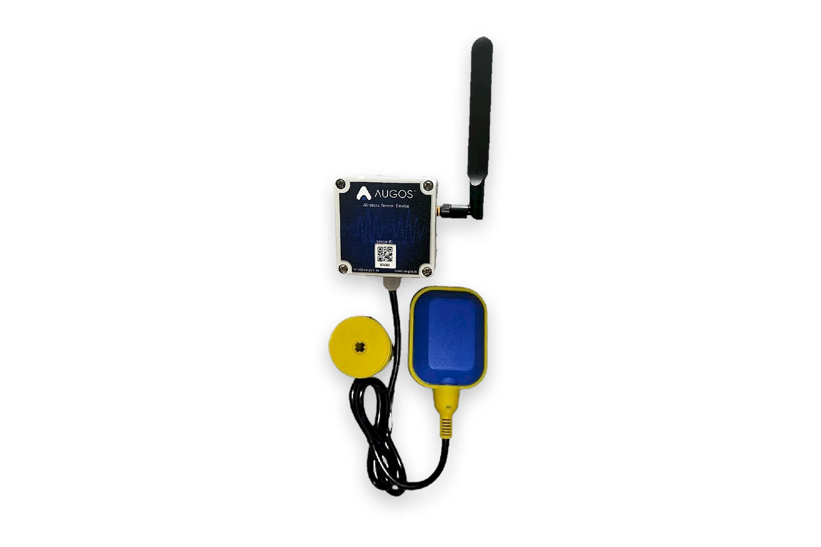
A float switch in a tank has nothing to power a Waterman with, and often nothing worth wiring one to. The kit replaces the tank-end unit with the Augos Wireless State Sensor: a sealed, battery-powered sender that reads one dry contact and reports it to a Waterman at the pump.
The sensor is fully potted and sealed to IP69 in an 80 × 80 × 55 mm enclosure, with a cable gland for the switch cable and a screw-in stubby antenna. Where it has to sit low or behind steel, the antenna can be swapped for a 5 m cable and a high-range antenna. It runs on a replaceable 3.6 V 7 500 mAh lithium thionyl chloride cell, rated for a minimum of four years. There is nothing to set at the sensor and nothing to keep charged.
A float switch with cable and counterweight is available with the kit, but any dry contact does the job: an existing float, a pressure switch, a level controller's output relay or a spare auxiliary contact.
How it behaves. The sensor transmits the moment the contact changes, and repeats its state every five minutes as a heartbeat. The Waterman's relay follows the contact: closed while the tank is calling for water, open when it is full. If nothing is heard from the sensor for fifteen minutes, the relay opens and the pump stops, so a flat battery or a damaged aerial ends with the pump off rather than running blind. When the sensor is heard again, the relay picks up the contact state and carries on by itself. Losing power at the Waterman also leaves the relay open, because it is a normally-open contact.
Note the difference in timing from a Waterman pair: a Waterman heartbeats every 15 seconds and drops the far outputs after 3 minutes of silence, while the battery sensor heartbeats every 5 minutes and the Waterman drops the relay after 15 minutes. The sensor's longer interval is what buys the battery life.
What the screen shows. The Waterman's display carries the paired sensor's serial number, the state of the switch at the tank, how long ago the last message arrived, the signal strength of that message and the state of the pump relay. It is enough to commission the installation and to fault-find it later without a laptop or a phone.
Pairing. Fit the jumper in the settings position and press Reset, the same procedure as changing the DIP settings. The screen goes into pairing mode. At the sensor, close, open and close the contact again: lift and drop the float, or bridge the terminals. The Waterman learns that sensor's serial number and shows it. Move the jumper back to its default position and the unit runs. The pairing is kept through a power failure, and pairing a different sensor is the same three steps again.
Powering the Waterman. The sensor looks after itself; the Waterman needs a supply, and there are three ways to give it one.
| What's available | What you use |
|---|---|
| A DC supply already at the pump | Any clean 7-20 V DC source able to give 500 mA, wired into +12V IN and GND. |
| 230 V AC at the pump | An Augos-supplied 230 V AC to 12 V DC adaptor. The simplest option wherever there is a socket. |
| No supply at the mounting point | A 20 W solar panel, charge controller and 12 V 8 Ah battery in a weatherproof enclosure. Also the answer where the box has to go up high for line of sight. |
Starting the pump follows the same three cases as any other Waterman installation, set out in switching the pump.
6 · How the units are arranged
| Arrangement | How it behaves |
|---|---|
| A pair | Two units, each one the other's opposite number. Whatever goes into the first comes out of the second, and whatever goes into the second comes out of the first, both directions at the same time. Both units are set to the same mode, channel, spreading factor and ID so they only talk to each other. |
| One receiver and up to seven senders | Use this where several places have to report to one. The receiver sits at the pump or the main board. Each sender sits at a tank, a pivot or a load. The receiver's relay closes while any one of the senders has its input closed, so the pump runs as long as any tank is calling for water. On the sensor channel the receiver puts out the lowest reading among the senders whose input is closed, which is how the pump ends up working to the line that is struggling most. A sender that has not been heard from for three minutes drops out of that picture until it comes back. It works the other way too: whatever is wired into the receiver's own input is copied to all seven senders at once, which is how one contact at the main board sheds seven loads across the site. |
| One unit repeating for another | Where two units can't see each other, a third one that can see both is switched to repeater mode and passes their messages along. Any sender can be set to do this, so there's no separate repeater to buy. A receiver can't, because it is always the destination. |
| A Waterman and a battery sensor | The tank-to-pump kit. One Waterman, one paired state sensor, no supply needed at the sensor end. |
7 · Specifications
| Model | Augos Waterman Rev 3 (AT-00-39) |
|---|---|
| Radio | LoRa, 433 MHz licence-free band, 8 channels, encrypted with error correction |
| Range | Up to 15 km line-of-sight per hop, extendable with a repeater |
| Data rate | 0.5 to 3.1 kbps, by spreading factor |
| Network modes | One-to-one · Many-to-one, one receiver and up to seven senders · Repeater |
| Digital input | 1 × dry contact, switch or relay contact only, no voltage |
| Digital output | 1 × 12 V relay, N/O dry contact, max 24 V DC. Pilot duty only: it switches the DC coil of a contactor or interposing relay, or a drive input. Never AC, never above 24 V DC |
| Analogue input | 1 × 1-5 V or 4-20 mA, switch-selectable |
| Analogue output | 1 × 0-5 V, reproducing the far analogue input across 0-100% |
| Serial | RS-485 Modbus RTU mirror, messages up to 60 bytes |
| Update behaviour | Sends on input change, plus a 15-second heartbeat; outputs follow on receipt |
| Link supervision | Unit marked disconnected after 3 minutes of silence; outputs return to open and 0 V |
| Display | 0.96" OLED showing mode, ID, message age, signal strength and live I/O; TX/RX, running and error LEDs |
| Configuration | DIP switches for mode, ID, channel, spreading factor and analogue type, protected by a jumper |
| Antenna | 5 m cable and high-range antenna as standard; 10 m and 20 m cables available |
| Power | 7-20 V DC, 12 V nominal, 500 mA minimum; solar kit or AC/DC adaptor |
| Operating temperature | -20°C to +85°C |
| Enclosure | Weatherproof outdoor housing, flange mount, external antenna connector |
Augos Wireless State Sensor
| Input | 1 × dry contact: float switch, or any switch or relay contact, no voltage |
|---|---|
| Radio | LoRa 433 MHz, paired to one Waterman, up to 15 km line of sight |
| Reporting | On every change of state, plus a 5-minute heartbeat |
| Link supervision | The paired Waterman opens its relay 15 minutes after the last message |
| Battery | 3.6 V 7 500 mAh LiSOCl₂, user-replaceable, four-year minimum life |
| Enclosure | Fully potted and sealed, IP69, 80 × 80 × 55 mm, cable gland for the switch cable |
| Antenna | Screw-in stubby antenna; optional 5 m cable with high-range antenna |
| Configuration | None at the sensor. It pairs to the Waterman by toggling the switch |
8 · Range and channels
| Spreading factor | Bit rate | Typical range |
|---|---|---|
| SF8 | 3.1 kbps | 3 km |
| SF9 | 1.8 kbps | 6 km |
| SF10 | 1.0 kbps | 10 km |
| SF11 | 0.5 kbps | 15 km |
| Channel | 0 | 1 | 2 | 3 | 4 | 5 | 6 | 7 |
|---|---|---|---|---|---|---|---|---|
| Frequency (MHz) | 433.1 | 433.3 | 433.5 | 433.7 | 433.9 | 434.1 | 434.3 | 434.5 |
Those ranges are line of sight, and what you actually get depends on the ground between the two aerials. The spreading factor is how slowly the radio talks: slower carries further, faster updates sooner. Set it for the longest link in the network. Units that need to talk to each other have to be on the same mode, channel and spreading factor, and a pair shares an ID as well. Give each pair or group in the same area a different combination so they don't talk over one another.
Where the two ends can't see each other, height usually solves it before a repeater does. A longer antenna cable that puts the aerial on a roof, a pole or the top of a tank is the cheaper fix; a sender in between set to repeat is the answer when the ground itself is in the way.
9 · What we need to quote
Most of a Waterman installation is decided by four questions, and the answers are what we need before we can put a kit together.
How far apart are the two ends, and can they see each other? That sets the spreading factor and tells us whether the standard 5 m antenna cable is enough or the aerial has to go up on a 10 m or 20 m one. If the ground is in the way, one of the units becomes a repeater or a third one goes in between.
What is there to power the unit with at each end? An existing 7-20 V DC supply, a 230 V socket for the AC/DC adaptor, or nothing at all, in which case it takes the solar kit. A battery state sensor needs nothing.
How is the pump or the load switched today? No contactor, an existing contactor, or a VSD. Each one needs a different thing from you: the pump kW or breaker rating if we are supplying the contactor, the coil voltage off the existing contactor if there is one, or confirmation that the drive has a free digital input on 24 V DC or less. The detail is in switching the pump.
What has to travel across the link? A contact, a 4-20 mA or 1-5 V sensor signal, Modbus, or some combination. One unit carries one of each, so more than one contact in the same direction means more than one link, or a Many-to-one group.
A tank-to-pump kit put together from those answers is typically: a state sensor, a float switch if there isn't already a contact at the tank, a Waterman, whichever power option suits the pump house, and a contactor if there is nothing to switch the pump with.
Common questions
Does it need the Augos platform?
No. Two units work on their own, with no SIM and no gateway, so a borehole 10 km out with no cellular signal runs the same as one next to the office. It has no connection to the Augos platform at all: there is no dashboard, no history and no alerts on a Waterman link, and everything it tells you it tells you on the screen on the unit. Those come with the Airswitch under Intelligent control instead.
How far will it reach?
Up to 15 km a hop if the two aerials can see each other. The figures are line of sight and depend on the terrain. Where one unit can't see the one it needs to talk to, put the aerial higher on a longer cable, or set a third sender in between to pass the messages along.
What happens if the radio link fails?
Between two Watermans, after three minutes without a message the relay at the far end opens and the sensor output falls to zero. On a tank-to-pump kit, where the sensor only reports every five minutes, the Waterman opens its relay after fifteen. Either way, wire the circuit so that open is the safe position.
Can the Waterman switch my pump directly?
No, and it should not switch a 230 V contactor coil either. Its output is a 12 V relay giving a dry contact for DC circuits up to 24 V. It switches the DC coil of a contactor, the DC coil of an interposing relay, or a drive's digital input, and those switch the motor. See switching the pump.
What do you need to know to supply a contactor?
The pump motor rating in kW, or the breaker or overload rating in amps, and whether the supply is 230 V single phase or 400 V three phase. If a contactor is already installed we need its coil voltage instead, printed next to the A1 and A2 terminals.
Can it carry more than an on-off signal?
Yes, but not as a number. Every unit has a sensor channel for a 4-20 mA or 1-5 V transmitter, and it comes out at the other end as 0 to 5 V across the transmitter's full range, for the drive or controller to scale. There's also an RS-485 port that passes Modbus RTU straight through, so you can poll a remote meter or controller as though it were wired to you.
How long does the battery sensor last, and can I change it?
A minimum of four years on a 3.6 V 7 500 mAh lithium cell, and yes, the cell is replaceable. Nothing else at the tank needs power or maintenance.
Do I have to buy your float switch?
No. A float switch, cable and counterweight are available with the kit, but the sensor takes any dry contact: an existing float, a pressure switch, a level controller's relay or a spare auxiliary contact.
How do I pair a sensor to a Waterman?
Jumper in the settings position, press Reset, then close, open and close the contact at the sensor. The Waterman shows the serial number it has learnt. Move the jumper back and it runs. The pairing survives a power failure.
Do I need a radio licence?
No. It runs on the 433 MHz licence-free band.
Is it safe to use for a trip?
Treat it as a control signal, not a protection device. Anything that has to trip for safety belongs in hardwired protection at the machine itself. The cut-out on a dead link limits how long one can go unnoticed, but it doesn't make a radio link a substitute for a trip circuit.